Archive for October 2012

2007 Dodge Nitro R/T wheel alignment

Description of wheel alignment Note: suspension components with rubber/urethane bushings should be tightened with vehicle in normal ride height. It is important to have the sources support the weight of the vehicle when the fastener is tightened. If the springs are not their usual ride, ride comfort of the car can be affected and may occur premature bushing wear. Convergence includes the correct positioning of the wheel relative to the vehicle. Positioning is done through adjustments to the suspension and steering linkage.


Alignment is necessary for efficient management, good directional stability and minimize tire wear. The most important measure of alignment are caster, camber and toe. Warning: never attempt to change the suspension or steering components by heating or bending. Note: may require periodic lubrication of front suspension/Steering system components. Rubber bushing should never be lubricated. Refer to LUBRICATION maintenance & for recommended maintenance schedule. Operation wheel alignment CASTER is forward or backward tilt of the Steering knuckle from the vertical. Tilt the top of the knuckle forward provides negative Caster. Tilt the top of the knuckle directed provides positive Caster. Positive caster promotes stability. This angle allows the front wheel to return to forward position after turns. See fig. 1 BULGE inward or outward tilt of the wheel relative to the center of the car. Tilt the top of the wheel inside has negative camber. Tilt the top of the outside wheel provides a positive camber.


Incorrect camber will wear inside or outside edge of the tire. Cm. Fig. 1 thumb the difference between leading and trailing edges inside the inside edges of the front tires. The Cape from the unreliable steering wheel, tyre wear uneven and the Centre of the steering wheel. Cape final alignment correction is steering the front wheel. See fig. 1 the thrust angle is the angle of the rear axle to the centreline of the vehicle. Wrong thrust angle can cause the center of the Steering and excessive wear of the tyres. This angle adjustable, no damaged components must be replaced to eliminate the thrust angle. Cm. Download

Read More 2007 Dodge Nitro R/T wheel alignment
Posted in |

2007 Dodge Nitro R/T transfer case removal disassembly

1. raise the vehicle. Warning: do not let hang cardan shafts attached at the end. Joint damage may result. 2.3. 4.5. Remove the front and rear propeller shafts. Refer to disposal. Transfer support with Jack. Remove the Rear crossmember and skid plate, if applicable. Disabling a case deflector hose (4). Cm. Fig. 2.6. 7.8. 9.10. Disconnect the wiring connector from the shift motor, if necessary. Support for transfer of the case to the transmission Jack and secure with chains. Remove the nuts (2) giving a transfer case (1) gear box (3). Pull the transfer case and Jack turned to disengage transfer case.


Remove the transfer case out from under the car. Disassembling the case transfer case to transmission position MP140 shallow drain pan. Remove the drain plug (2) and drain the grease. 2. using the bracket C-3281 (1), remove the rear output flange nut. 3. remove the rear output shaft flange (1) out of the main shaft (2). If the flange is difficult to remove manually, remove it with a separator or standard bearing two jaw puller. Be sure to eject the tool securely positioned on the flange. Download

Read More 2007 Dodge Nitro R/T transfer case removal disassembly
Posted in |

2007 Dodge Nitro R/T FLUID LEVEL CONTROL DESCRIPTION

The oil level control is located on the electrohydraulic unit (4) and consists of the float (5) which is integrated into the electrohydraulic unit. The float is positioned to plug the opening (6) between the oil gallery (2) and gearset chamber (1) so that the rotating gearsets do not splash about in oil as the oil level rises. The oil level control reduces power loss and prevents oil from being thrown out of the transmission housing at high oil temperatures. See Fig. 182.


OPERATION FLUID LEVEL CONTROL With low oil levels, the lubricating oil which flows constantly out of the gearset, flows back to oil gallery (2) though the opening (6) If the oil level rises, the oil presses the float (5) against the housing opening (6). The float (5) therefore separates the oil gallery (2) from the gearset chamber (1). The lubricating oil which continues to flow out of the gearsets is thrown against the housing wall, incorporated by the rotating parts and flows back into the oil gallery (2) through the upper opening (arrow). See Fig. 183. DIAGNOSIS AND TESTING CAUSES OF BURNT FLUID Burnt, discolored fluid is a result of overheating which has three primary causes. Internal clutch slippage, usually caused by low line pressure, inadequate clutch apply pressure, or clutch seal failure. A result of restricted fluid flow through the main and/or auxiliary cooler. This condition is usually the result of a faulty or improperly installed drainback valve, a damaged oil cooler, or severe restrictions in the coolers and lines caused by debris or kinked lines. Heavy duty operation with a vehicle not properly equipped for this type of operation. download

Read More 2007 Dodge Nitro R/T FLUID LEVEL CONTROL DESCRIPTION
Posted in |

2007 Dodge Nitro R/T CONVERTER-TORQUE DESCRIPTION

CAUTION: The torque converter must be replaced if a transmission failure resulted in large amounts of metal or fiber contamination in the fluid. The torque converter is a hydraulic device that couples the engine crankshaft to the transmission. The torque converter consists of an outer shell with an internal turbine (1), a stator (3), an overrunning clutch, an impeller (2), and an electronically applied converter clutch. The converter clutch provides reduced engine speed and greater fuel economy when engaged. Clutch engagement also provides reduced transmission fluid temperatures.


The converter clutch engages in third through fifth gears. The torque converter hub drives the transmission oil (fluid) pump. See Fig. 267. A turbine damper (6) has been added for some applications to help improve vehicle noise, vibration, and harshness (NVH) characteristics. The torque converter is a sealed, welded unit that is not repairable and is serviced as an assembly. download

Read More 2007 Dodge Nitro R/T CONVERTER-TORQUE DESCRIPTION
Posted in |

2006 Dodge RAM 1500 P2122 accelerator pedal position sensor

The brake pedal is pressed or fails. Accelerating the speed and engine power are limited. One trip fault code and installs within 5 seconds. And so light blinks. Possible causes (F855) 5-volt power supply chain breakage (F855) 5-volt power supply shorted to ground (K23) APP No. 1 signal-chain sensor open (K23) APP # 1 sensor signal circuit shorted (K23) APP sensor no. 1 signal circuit shorted in the APP (K167) sensor no. 1 return circuit (K23) APP sensor no. 1 signal circuit shorted (K400) Appendix # 2 return the APP sensor PCM schemes always follow the troubleshooting of the PKK before continuing. DIAGNOSTIC TEST 1. APP sensor below 0.25 Volts, ignition, engine not running.


With scan tool read the # 1 APP voltage sensor. Question: is the voltage below 0.25 volts? Yes: go to 2 No 11: go to 2. Food chain (F855) 5-Volt when monitoring: with the ignition on and no other APPS # 1 DTCS present. Set condition: when the APP # 1 sensor voltage too low. The engine will idle, if turn ignition off. Disconnect the sensor connector APP strap. Ignition on, engine not running. Measure the voltage on the power supply circuit (F855) 5-volt in-APP sensor connectors. Question: is the voltage between 4.5 and 5.2 volts? Yes: do not go 3: jump to 8 3. ACCELERATOR PEDAL POSITION SENSOR


Download

Read More 2006 Dodge RAM 1500 P2122 accelerator pedal position sensor
Posted in |

2001 Dodge Durango VEHICLE THEFT SECURITY SYSTEM DESCRIPTION

2001 Dodge Durango VEHICLE THEFT SECURITY SYSTEM DESCRIPTION Anti-Theft Systems – Dakota & Durango DESCRIPTION VEHICLE THEFT SECURITY SYSTEM Vehicle Theft Security System (VTSS) provides perimeter protection against unauthorized use or tampering by monitoring vehicle’s doors, ignition system and liftgate (Durango). VTSS flashes headlights and sounds horn if any door, hood or liftgate (Durango) is opened without using valid key or Remote Keyless Entry (RKE) system. VTSS is controlled by Central Timer Module (CTM). CTM is located behind left side kick panel. VTSS is also equipped with a power-up mode. If battery is disconnected or loses power while VTSS is armed, VTSS system remains armed when power is restored. A tamper alert signal is sounded on vehicle entry if VTSS was triggered while away from vehicle.


Horn will sound 3 times, alerting owner VTSS was triggered. SENTRY KEY IMMOBILIZER SYSTEM If vehicle is equipped with optional Sentry Key Immobilizer System (SKIS), ignition key will have a Gray molded rubber cap. Models not equipped with optional SKIS will have a Black molded rubber cap on the head of the ignition key. SKIS consists of the Sentry Key Immobilizer Module (SKIM), sentry transponder keys, SECURITY indicator LED and Powertrain Control Module (PCM). SKIM is located under steering column shrouds, near ignition lock cylinder. Transponder is located in ignition key. See Fig. 1 . If an invalid ignition key is used, SKIM will send invalid signal to PCM, causing engine to start and run for 2 seconds, then stop. If vehicle is started with invalid keys 6 times in a row, vehicle will shut down until correct key is used.


download

Read More 2001 Dodge Durango VEHICLE THEFT SECURITY SYSTEM DESCRIPTION
Posted in |

2001 Dodge Ram 2500 bearing noise testing and verification

Mechanism of injury. The differential side gears and pinions can be checked by turning the vehicle. They usually do not cause noise during the avant-garde movement when unloading gear. Side gears are loaded during the twists and turns of the vehicle. Worn pinion shaft can also cause binding or knocking noise. Bearing noise bearings, shaft, differential and axle gear may produce noise if worn or damaged. Bearing noise may be whining, growling sound. Pinion bearings have a constant field. This noise is only changed when the speed of the vehicle. Pinion bearing noise will be higher pitched because it rotates more rapidly. Drive the car and load differential. If the bearing noise occurs, the pinion rear bearing is the source of the noise. If the bearing noise heard during the coast bearing the front gears is the source. Worn or damaged differential bearings normally produce noise low.


Differential bearing noise similar to the noise of the gear. Step differential bearing noise is constant depends only on the speed of the vehicle. Axle shaft bearings produce noise and vibrations when worn or damaged. The noise usually changes when loading the bearings. Road test the vehicle. Turn the car sharply to the left and right. This will load the bearings and change the level of noise. Where the minor axis, given the damage, the noise is usually not noticeable at speeds of 30 mph above. low detonation velocity of low detonation velocity is usually caused by wear crosses or worn side gear bearing ring. Worn pinion shaft bore is also a cause of low speed knock. VIBRATION vibration on the rear face of the vehicle, usually caused by a damaged drive shaft. There is no drive shaft balance value. Worn or balance wheel. Loose wheel lug nuts. Be a U-joint (s). Loose/broken coil springs. Damage to the axle shaft bearing (s). 2001 Dodge Ram 2500 bearing noise testing and verification  Download

Read More 2001 Dodge Ram 2500 bearing noise testing and verification
Posted in |

2000 Dodge RAM 1500 Van fuel leak down pressure test

Use this test in combination with pressure test the fuel pump and the fuel capacity Test. check valve pump operation: the electric fuel pump outlet contains a one-way valve to prevent fuel flow back into the tank and to maintain fuel supply line pressure (engine warm) when the pump is not working. It is also used to keep the fuel supply line, full of gasoline when the pump is not working. After the vehicle has cooled down, the fuel pressure may drop to 0 psi (cold fluid contracts), but liquid gasoline will remain in the fuel supply line between the check valve and fuel injectors. Fuel pressure, which dropped to 0 psi on a cooled down vehicle (engine off) is a normal condition.


Where is the electric fuel pump, fuel pressure should immediately (1-2 seconds) rise to specification. Abnormally long periods of cranking to restart a warm engine, which was closed for a short period of time can be caused by: fuel pressure, bleeding in the past, injector (s). Fuel pressure, bleeding in the past, the valve in the fuel pump module. 1. disconnect the fuel line at the fuel rail. Refer to fuel tubes/lines/hoses and clamps for procedures. On some engines cleaner housing air removal may be required before the fuel line separation. 2. get the right fuel line pressure test hose tool adapter. Tool number 6539 is used for 5/16 "tubing and tool room 6631 is used for 3/8 fuel lines. Fig. 7 connect the adapter tool (typical) 3. Connect the correct fuel line pressure test hose between tool adapter disconnected fuel line and fuel rail (fig. 7). 4. connect 0-414 kPa (0-60 psi) test fuel pressure gauges (gauge set 5069) to test for the appropriate adapter tool. DRB III Scan Tool together with the PEP module pressure 500 psi port adapter and sensor test can also used instead of the fuel pressure sensor.


2000 Dodge RAM 1500 Van fuel leak down pressure test Download

Read More 2000 Dodge RAM 1500 Van fuel leak down pressure test
Posted in |

2000 Dodge Dakota UPPER BALL JOINT DIAGNOSIS

1. Position a floor jack under the right side lower suspension arm. 2. Raise the wheel and allow the tire to lightly contact the floor (vehicle weight relieved from the tire). 3. Mount a dial indicator (Special Tool C3339 or equivalent) solidly on the upper suspension arm (Fig. 1 ). Fig. 1: Right Side View Of Suspension (Wheel/Tire Removed For Clarity) 4. Position the dial indicator plunger against the back side of the steering knuckle boss for the upper ball joint (Fig. 1 ). 5. Zero the dial indicator while pulling outward on the top of the tire. 6. While an assistant watches the dial indicator gauge, grasp the top of the tire and push inward. Record the dial indicator reading observed from the full outward to full inward position. 7. Repeat Step #1 through Step #6 on the left side upper ball joint.


When both the left and the right upper ball joints have been inspected, proceed to Step #8. 8. Based on the results recorded in Step #6: a. If the lateral movement on both upper ball joints is less than 0.060 in. (1.52 mm), no further action is required. Remove the dial indicator, lower the wheel and return the vehicle to the owner. b. If the lateral movement on either of the upper ball joints is greater than 0.060 in. (1.52 mm), replace both upper ball joints as described in the Repair Procedure.


2000 Dodge Dakota UPPER BALL JOINT DIAGNOSIS download

Read More 2000 Dodge Dakota UPPER BALL JOINT DIAGNOSIS
Posted in |

Yamaha XZF R6-(L-CL) Manual

The guide for Yamaha XZF R6-(L-CL) Coating: -introduction-appliances-entertainment systems-climate control-the lights – driver Controls – locks and security – the security restrictions of seating and is driving – maintenance and fuel specifications – the engine Bay – informations – replenishment capabilities – grease specifications-accessories-index
download here

Read More Yamaha XZF R6-(L-CL) Manual
Posted in |

New GTV and spider buyers guide

This article is about New GTV and spider buyers guide,  the Alfa Romeo GTV and spider models launched in 1995, which remained in production until 2005. The Pininfarina design was fat at that time and still looks fresh today. Both models share the same front end and there were some mechanical part its commonality with the 155 loosely based basics to Fiat Tempra.

Although Alfa front wheel vehicles produced Romeo since 1972, the first Coupé and spider were so equipped models. With the previous Alfetta GTV was out of production since 1986 and was the series 4 spider since 1992 no immediate predecessor, to be compared with. However, the first reaction was received with both
models tempered praise in the press conveniently (keep in mind this was the Alfa were time nor restore and sales were very poor).

New GTV and spider buyers guide Download
Read More New GTV and spider buyers guide
Posted in |

VAUXHALL ASTRA ZAFIRA PETROL NEW MANUAL 3758

Vauxhall/Opel Astra & Zafira Petrol (Feb 98 – Apr 04) R-04 reg. Astra Hatchback, Saloon & Estate, & Zafira MPV, inc. special/limited editions.
Does NOT cover Coupe or Convertible, new range introduced May 2004, Diesel or bi-fuel models
1.4 litre (1389cc), 1.6 litre (1598cc), 1.8 litre (1796cc), 2.0 litre (1998cc) & 2.2 litre (2198cc).
Does NOT cover 1.6 litre ‘Twinport’ or 2.0 litre turbo engines

Read More VAUXHALL ASTRA ZAFIRA PETROL NEW MANUAL 3758
Posted in |

VAUXHALL ZAFIRA – MISFIRE PROBLEM

Fault
Caller reported to the helpline that the vehicle had developed a misfire under load, especially when the engine was hot. It was also mentioned that as the misfire occurred, the engine would suddenly appear to run on only 3 cylinders. The engine running on 3 cylinders would continue until the ignition was switched OFF. If the engine was re-started the engine would run on all 4 cylinders again until the misfire reoccurred under load, and then the engine once again appeared to be running on only 3 cylinders.
Cause
The initial misfire fault under load was finally traced to cylinder no 1 on the engine. The fault was caused by a poor output from the DIS ignition coil pack fitted to the vehicle. Upon testing the vehicle, it was discovered that when the misfire occurred on cylinder no 1, the Multec engine management ECM would switch OFF the fuel injector for the affected cylinder. The caller reported that when the engine was switched OFF and then restarted the misfire would disappear, and the fuel injector for cylinder no 1 would operate normally again download

Read More VAUXHALL ZAFIRA – MISFIRE PROBLEM
Posted in |

Vauxhall Astra / Cavalier (Fwd) Water Pump Seal Leakage

Coolant loss through the water pump bearing seal is commonly caused by a faulty cooling system pressure cap. With certain designs of the plastic pressure cap, if the cooling system overheats distortion of the pressure relief valve in the cap can cause the valve to stick and result in excessive pressure in the cooling system. It is recommended that the coolant pressure cap is always checked for correct operation, prior to the fitment of a new water pump. Thermostat Testing In order to confirm if the thermostat is operating as required, the correct testing procedure should be adopted.


Equipment required : 1) A container of undiluted anti-freeze mixture, to allow the temperature of the liquid to be raised above boiling point. (DO NOT use plain water). 2) A suitable heating element to raise the temperature of the liquid. 3) An accurately calibrated thermometer, with a range suitable for the thermostat to be tested. Testing Lower the thermostat into the container of anti-freeze, along with the thermometer, and heat the liquid slowly to the temperature marked on the thermostat, e.g 88 degrees, whilst agitating the thermostat. Let the temperature remain stable for one minute, then check for initial opening of the thermostat valve, Note: The valve will only just crack open at this temperature. Increase the temperature of the liquid to at least 14 degrees above the initial opening temperature, e.g.102 degrees, again allow one minute, then check the valve is fully opened. Allow the liquid to cool to below the initial opening temperature, then check that the valve is fully closed. Opening and fully open temperatures should be within plus or minus 2 degrees of those stated A build up of sediment coating on the thermostat can adversely effect the performance of the thermostat. download

Read More Vauxhall Astra / Cavalier (Fwd) Water Pump Seal Leakage
Posted in |

1996-2000 Vauxhall Corsa B/Combo Timing belt replacement

Special Precautions Special Precautions Disconnect battery earth lead. DO NOT turn crankshaft or camshaft when timing belt removed. Remove glow plugs to ease turning engine. Turn engine in normal direction of rotation (unless otherwise stated).


DO NOT turn engine via camshaft or other sprockets. Observe all tightening torques. Check diesel injection pump timing after belt replacement. Removal Removal 1. Support engine. 2. Remove: Air filter and air intake hoses. Auxiliary drive belts. RH engine mounting. Vacuum pipe bracket. Timing belt upper cover [1]. 3. Turn crankshaft clockwise to TDC on No.1 cylinder. Ensure crankshaft sprocket timing marks aligned [2]. 4. Insert M6 x 1,00 bolt in camshaft sprocket and M8 x 1,25 bolt in injection pump sprocket to lock sprockets in position [3]. NOTE: If locating holes not aligned: Turn crankshaft one turn. 5. Remove: Crankshaft pulley (4 bolts). Timing belt lower cover [4]. 6. Slacken tensioner bolts [6]. Remove tensioner spring [5]. 7. Move tensioner pulley away from belt. Lightly tighten bolts. 8. Remove timing belt. Installation Installation 1. 2. 3. 4. 5. Use crankshaft pulley to check TDC marks aligned [2]. Ensure locking bolts located correctly [3]. Fit timing belt in clockwise direction, starting at crankshaft sprocket. Ensure belt is taut between sprockets. Temporarily fit crankshaft pulley.


Ensure timing marks aligned [2]. Fit tensioner spring [5]. Corsa-B/Corsavan/Combo: Slacken tensioner bolts [6]. Allow tensioner to operate. Remove locking bolts [3]. Tighten tensioner bolts to 19 Nm [6]. Turn crankshaft slowly two turns clockwise. Ensure timing marks aligned [2]. 6. Astra-F/Vectra/Cavalier: Slacken tensioner bolts [6]. Temporarily fit crankshaft pulley. Remove locking bolts [3]. Turn crankshaft 60° anti-clockwise (against normal direction of rotation) [7]. Tighten tensioner bolts to 19 Nm [6]. Turn crankshaft slowly two turns + 60° clockwise until timing marks aligned [2]. 7. 8. 9. 10. 11. Ensure timing marks aligned [2]. Ensure locking bolts can be inserted in sprockets [3]. If not: Repeat tensioning procedure. Remove crankshaft pulley. Fit timing belt lower cover [4]. Fit crankshaft pulley. Tighten bolts to 20 Nm. Install components in reverse order of removal. 

download
Read More 1996-2000 Vauxhall Corsa B/Combo Timing belt replacement
Posted in |

1995 – 2001 VAUXHALL Vectra 2.5 i Poor starting from cold

Disconnect battery. Disconnect harness multi-plug from engine coolant temperature (ECT) sensor Fig.1 [2] . Disconnect harness multi-plug from mass air flow (MAF) sensor Fig.1 [4] . Remove protective cover Fig.1 [1] . Remove plastic tube from wiring harness Fig.1 [3] . Remove insulation tape from wiring harness. Cut engine coolant temperature (ECT) sensor wiring and remove from cable ducting.


Cut new engine coolant temperature (ECT) sensor wiring a minimum of 120 mm long. Fit new wiring harness multi-plug to wires Fig.2. Repair wiring with repair kit listed. Seal with insulation tape Fig.3. Remove engine coolant temperature (ECT) sensor. Fit modified engine coolant temperature (ECT) sensor. Tightening torque: 18 Nm. Refit wiring harness multi-plug. Reconnect battery. Erase fault memory. 1995 – 2001 VAUXHALL Vectra 2.5 i Poor starting from colddownload

Read More 1995 – 2001 VAUXHALL Vectra 2.5 i Poor starting from cold
Posted in |

Vauxhall VECTRA Owner’s Manual Operation, Safety and Maintenance

To lower Turn rotary switch to d. Posit ion memory After the ignition has been switched on, the sunroof c an be automatically returned to its last position b y briefly pressing the rotary switch. Safety function If the sunroof encounters resistance during automatic closing, it is immediately stopped and opened again, as long as the vehicle is stationary. Operated using rotary switch in the overhead control panel.


To open Turn the rotary switch to any position between d and ü. The sunroof will automatically move to the desired position. When the switch is in position ü , the sunroof is fully opened . Com fort position Set rotary switch to position f.


With the roof in this position, w ind noise is reduced. To close: Turn rotary switch to d. 9 Warning Closing sunroof from outside To close the sunroof from outside with the remote control: Press button p until the sunroof is closed. If the electric windows 3 are to be closed from outside the vehicle, but the sunroof is to be left op en, briefly press the rotary switch before switching off the ignition.  download

Read More Vauxhall VECTRA Owner’s Manual Operation, Safety and Maintenance
Posted in |

DIAGNOSIS AND REPAIR Hyundai SONATA NF XM SET TOP BOX

PROCEDURE: A). When diagnosing a vehicle with an inoperative XM Set Top Box, check for water intrusion into the set top box. If no water damage is noted proceed with normal diagnostics. If water damage is noted then proceed to Step B. B). 1. Remove Set Top Box a. Gain access to trunk and remove trunk pad/carpet b. Remove 2 mounting screws attaching set top box to the body c. Disconnect box from harness 2. Visually inspect body for signs of water intrusion.


Without Sunroof or AMP With Sunroof and AMP 3. Note that water may enter at body seams, screw holes, body plugs, or weld joints. 4. Reseal all joints and any other suspect water entry point with appropriate body sealer sealant.

Hyundai SONATA NF XM SET TOP BOX DIAGNOSIS AND REPAIR download
Read More DIAGNOSIS AND REPAIR Hyundai SONATA NF XM SET TOP BOX
Posted in |

3.8L M/T HYUNDAI GENESIS COUPE ENGINE RPM CONTROL LOGIC UPDATE

If the vehicle has been in storage for days, run the engine to ensure an adequate battery charge state for reliable update results. 2. Turn off all lamps (Do not leave head lamp switch in auto mode) and all accessories (including heater, A/C, blower, radio, seat warmer, defroster, etc.) to prevent the battery discharge during the update. 3. Perform the update with the ignition switch in the ON position. 4. Be careful not to disconnect any cables connected to the vehicle or scan tool during the update. 5. Do not start the engine during update. 6. Do not turn off the ignition switch during update. 1. Connect the power supply cable to the diagnostic terminal. NOTE: If attempting to perform the update with the power supply cable disconnected from the diagnostic terminal, make certain that the diagnostic terminal is charged enough for the update. If not, the update may fail in progress.


Therefore, it is strongly recommended to connect the power supply cable to the diagnostic terminal during the update procedure. 2. Connect the USB cable between the VCI and the diagnostic terminal. NOTE: When performing the update using the GDS, wireless communication between the VCI and the diagnostic terminal is NOT available. Therefore, be sure to connect the USB cable between the VCI and the diagnostic terminal. 3. Connect the 16-pin DLC cable from the VCI into the vehicle’s 16-pin connector under the driver side instrument panel. 4. Turn on the VCI and diagnostic terminal with the ignition key in the ON position. NOTE: Do not start the engine. download

Read More 3.8L M/T HYUNDAI GENESIS COUPE ENGINE RPM CONTROL LOGIC UPDATE
Posted in |

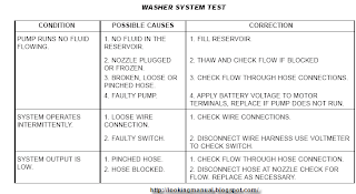
DIAGNOSIS AND TESTING - WASHER SYSTEM CHRYSLER

DIAGNOSIS AND TESTING - WASHER SYSTEM CHRYSLER
Whenever a windshield washer malfunction occurs, first verify that the washer pump connector and the multi-function switch, front wiper/washer switch connector is properly connected before starting diagnosis and testing. Also check the rear wiper/washer switch connection. Refer to WASHER SYSTEM TEST table.

FRONT WASHER NOZZLE
REMOVAL
(1) Open hood.
(2) Remove the underhood, rear hood silencer pad
fasteners.
(3) Disconnect the washer hose from the underside
of the front washer nozzle.
(4) Lower hood down.
(5) Using a plastic body filler spreader or equivalent
(credit card), gently place it underneath the
front of the washer nozzle. Be careful not to damage
the hood seal underneath the nozzle (Fig. 6).
(6) Rock the nozzle back and forth slightly to
release it from the hood panel.
INSTALLATION
(1) Place the nozzle into hood opening and snap
into place.
(2) Open hood.
(3) Connect the washer hose to the underside of
the washer nozzle.
(4) After connecting hose, check for proper system
function and to assure leak free connections by actuating
the front washer system switch from inside of
vehicle.
(5) Install the underhood, rear hood silencer pad
fasteners.
(6) Close hood.
(7) Verify system operation.
Read More DIAGNOSIS AND TESTING - WASHER SYSTEM CHRYSLER
Posted in |

DIAGNOSIS AND TESTING - FRONT WIPER CONDITIONS

DIAGNOSIS AND TESTING - FRONT WIPER CONDITIONS
The following is a list of general wiper motor system problems, the tests that are to be performed to locate the faulty part, and the corrective action to be taken. Whatever the problem, disconnect motor wire harness and clean the terminals, then connect motor wire harness and test. Refer to Wiring Diagrams for circuit information and connector call-outs.

MOTOR WILL NOT OPERATE ALL SWITCH
POSITIONS
(1) Check fuse 1, in the fuse block (Fig. 2).
(1 - FUSE 1 WIPER)
(a) If fuse is OK, go to Step 2.
(b) If fuse is defective, replace and check motor
operation in all switch positions.
(c) If motor is still inoperative and the fuse does
not blow, go to Step 2.
(d) If replacement fuse blows, go to Step 6.

(2) Disconnect motor harness connector.
(3) Check motor low speed. Using two jumper
wires, connect one jumper wire between the battery
positive terminal and terminal 4 of the motor connector.
Connect the other jumper wire to the battery
negative terminal and terminal 1 of the motor (Fig.
3). Check motor high speed, connect the positive
jumper wire to terminal 5 of the motor connector.
Connect the negative jumper wire to terminal 1 of
the motor.
Read More DIAGNOSIS AND TESTING - FRONT WIPER CONDITIONS
Posted in |

FRONT WINDSHIELD WIPERWASHER SWITCH LOCATION

FRONT WINDSHIELD WIPERWASHER SWITCH LOCATION
1 - TURN SIGNAL CONTROL STALK 5 - CANCELLING CAM
2 - HAZARD WARNING SWITCH 6 - PANEL DIMMER/INTERIOR LIGHT SWITCH
3 - WINDSHIELD WIPER/WASHER CONTROL 7 - EXTERIOR LIGHTING CONTROL/FOG LAMP
4 - WINDSHIELD WIPER/WASHER SWITCH RETAINING SCREWS. FRONT WINDSHIELD WASHER SYSTEM

This vehicle is equipped with an electrically operated windshield washer pump. The washers are operated by a switch in the multi-function switch control lever (Fig. 1). The lever is located on the right side of the steering column. The electric pump assembly is mounted directly to the reservoir. A permanently lubricated motor is coupled to an impeller type pump.

The pump and reservoir are serviced as separate assemblies. REAR WINDSHIELD WIPER SYSTEM The driver controls an electrically operated intermittent rear wiper system with the switch located on the instrument panel accessory switch bezel. The rear wiper is controlled by ignition switched battery current through a fuse in the fuse block, and will operate only when the ignition switch is in the Accessory or ON positions.

The intermittent rear wiper system allows the driver to select an intermittent wipe mode. The intermittent wipe mode delay time has a fixed delay interval of about four seconds between sweeps. This system also has a wipe-after-wash feature that operates the rear wiper for as long as the washer pump is energized, then provides about two additional sweeps of the wiper after the washer pump is de-energized. The rear wiper motor module operates on a separate non-switched battery current feed through a fuse in the fuse block.
Read More FRONT WINDSHIELD WIPERWASHER SWITCH LOCATION
Posted in |

CHRYSLER AIRBAG SYSTEM COMPONENT LOCATION

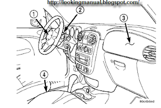
dual front airbag system
A dual front airbag system (Fig. 1) utilizes driver and passenger airbags. Both the driver and passenger airbags are certified to new federal regulations, which allows them to deploy with less force than prior airbags. The primary occupant restraints in this vehicle are the seat belts, which require active use by the vehicle occupants.

The front airbag system is a supplemental passive restraint that was designed and is intended to enhance the protection for the front seat occupants of the vehicle when used in conjunction with the seat belts. The driver airbag includes an inflatable airbag and an inflator unit behind a trim cover in the hub area of the steering wheel. The passenger airbag includes an inflatable airbag and an inflator unit behind an airbag door in the instrument panel above the glove box.

The dual front airbag system consists of the following components: ² Occupant Restraint Controller (ORC) ² Airbag indicator lamp. ² Clock Spring ² Driver and passenger airbags (including the airbag inflators).

1 - DRIVER AIRBAG
2 - CLOCK SPRING
3 - PASSENGER AIRBAG
4 - OCCUPANT RESTRAINT CONTROLLER (ORC)
Read More CHRYSLER AIRBAG SYSTEM COMPONENT LOCATION
Posted in |

Toyota 2L-T, 3L Engine Repair Manual Supplement

Toyota 2L-T, 3L Engine Repair Manual
this is Toyota 2L-T, 3L Engine Repair Manual inside is how to To assist you in finding your way through this manual, the Section Title and major heading are given at the top of every page. An INDEX is provided on the 1st page of each section to guide you to the item to be repaired. At the beginning of each section, PRECAUTIONS are given that pertain to all repair operations contained in that section. Read these precautions before starting any repair task. TROUBLESHOOTING tables are included for each system to help you diagnose the problem and find the cause. The repair for each possible cause is referenced in the remedy column to quickly lead you to the solution.

How to Use This Manual
The procedures are presented in a step-by-step format: #
• The illustration shows what to do and where to do it.
• The task heading tells what todo.
• The detailed text tells how to perform the task and gives other information such as specifications and warnings.
This format provides the experienced technician with a FAST TRACK to the information needed. The upper case task heading can be read at a glance when necessary, and the text below it provides detailed information. Important specifications and warnings always stand out in bold type.

GENERAL REPAIR INSTRUCTIONS
1. Use fender, seat and floor covers to keep the vehicle clean and prevent damage.
2. During disassembly, keep parts in order to facilitate reassembly.
3. Observe the following.
(a) Before performing electrical work, disconnect the negative (—) cable from the battery terminal.
(b) If it is necessary to disconnect the battery for inspection or repair, always disconnect the cable from the negative (—) terminal which is grounded to the vehicle body.
(c) To prevent damage to the battery terminal post, loos- en the terminal nut and raise the cable straight up without twisting or prying it.
(d) Clean the battery terminal posts and cable terminals with a shop rag. Do not scrape them with a file or other abrasive object.
(e) Install the cable terminal to the battery post with the nut loose, and tighten the nut after installation. Do not use a hammer to tap the terminal onto the post. (f) Be sure the cover for the positive (+) terminal is properly in place.
4. Check hose and wiring connectors to make sure that they are secure and correct.
5. Non-reusable parts
(a) Always replace cotter pins, gaskets, O-rings, oil seals, etc. with new ones.
(b) Non-reusable parts are indicated in the component illustrations by the ” ? ” symbol.

Download
Read More Toyota 2L-T, 3L Engine Repair Manual Supplement
Posted in |

Diesel maintenance manual 2008 Mercedes Benz AMG

2008 Mercedes Benz AMG service manual
In the pdf books including: – Engine Technical Data – Starting and Running – On the spot Maintenance – Checking the Engine – Scheduled Maintenance . this will show you how to maintenance your vehicle (2008 Mercedes Benz AMG ). please be carefully before you use it. we cannot quaranty.
you can download Diesel maintenance manual 2008 Mercedes Benz AMG from this source.
Read More Diesel maintenance manual 2008 Mercedes Benz AMG
Posted in |

2005 Nissan Pathfinder Owners Manual

To move the shift selector lever release the shift lock The shift selector lever can be moved to N Neutral However the steering wheel will be locked unless the ignition switch is turned to the ON position This allows the vehicle to be moved if the battery is discharged To push the shift lock release complete the following procedure.

WARNING If the selector lever cannot be moved from
the P Park position while the engine is running and the brake pedal is depressed the stop lights may not work Malfunctioning stop lights could cause an accident injuring yourself and others 5 12 Starting and driving.

the Overdrive switch to turn the Overdrive off The O D OFF indicator light in the instrument panel comes on at this time LSD0142 Overdrive switch Each time your vehicle is started the transmission is automatically reset to overdrive ON When driving conditions change depress the Overdrive switch to turn the Overdrive on Remember not to drive at high speeds for extended periods of time with the Overdrive off This reduces fuel economy ON With the engine running and the shift selector lever in the D Drive position the transmission upshifts into Overdrive as vehicle speed increases Overdrive does not engage until the engine has reached operating temperature Starting and driving.

Download
Read More 2005 Nissan Pathfinder Owners Manual
Posted in |

Pathfinder Owners Manual 2002 Nissan

Pathfinder Owners Manual 2002 Nissan
Engine serial number 9 13 Engine specifications 9 9 If your vehicle overheats 6 11 Starting the engine 5 9 Exhaust gas Carbon monoxide 5 2 F F M V S S certification label 9 13 Filter Air cleaner housing filter 8 23 Flashers See hazard warning flasher switch 2 23 Flat tire 6 2 Floor mat cleaning 7 4 Fluid Automatic transmission fluid ATF 8 16 Brake and clutch fluid 8 18 Brake fluid 8 18 Capacities and recommended fuel lubricants 9 2 Engine coolant 8 9 Engine oil.

Power steering fluid 8 18 Window washer fluid 8 20 10 2 01 9 21 R50 D V5 FM AM radio with cassette player and Compact Disc CD.

Pathfinder Owners Manual 2002 Nissan Download
Read More Pathfinder Owners Manual 2002 Nissan
Posted in |

Owner/service Manual for DUCATI ST4s

DUCATI ST4s
When the ignition key to OFF is selected, inhibits the immobilizer of operation of machine. When the ignition key, to rejected will start the engine does the following:
(1) If the CPU detects the code, which flashes briefly LED CODE on the instrument panel. This means that the immobilizer system captures the key code and engine ignition is enabled. When you press the START button, the engine is started.
Read More Owner/service Manual for DUCATI ST4s
Posted in |

Ducati 900SS Service Manual

Ducati 900SS raw riding sensation
Mike Hailwood 1978 drove children like me crazy on a Ducati 900 at the TT win and we are the adults who want these bikes today. The 900SS is a single-minded Sportster, which has been still feelings, not by which some have a name.
I 900SS go is pretty not so perfect as the earlier solo-seated wire wheels models, but it is still long and slender in glittering black and gold color. It's all so in 1978, as a prominent footballer bathroom. The lines and proportions of the classic Ducati half sports Panel clip-ons tour and long tank are sensational. The square engine cases uglier sisters the older and much sought after round case 750 engines, still well with smooth curves sit, which is the rest of the bike.

John Fallon of Mdina Italia, which us these original early Speedline converted wheel 900SS awarded, is expecting the bike has been updated, but the engine is unrestored (although a Lucas Rita electronic ignition at some point been incorporated). If this is the case, also put was to discover together in Borgo Panigale, Bologna, all those years, as I.

Download
Read More Ducati 900SS Service Manual
Posted in |

2002 PT cruiser remove the air box Replace the power steering sensor

2002 PT cruiser remove the air box Replace the power steering sensor
The guide for 2002 PT cruiser remove the air box Replace the power steering sensor. Power steering pressure sensor is accessed from under the car, It's located on the drivers side behind the engine on the steering rack. It's a bit messy to change but pretty easy to do

hope this post helpul for you.
Read More 2002 PT cruiser remove the air box Replace the power steering sensor
Posted in |
Powered by Blogger.

Search