DIAGNOSIS AND TESTING - FRONT WIPER CONDITIONS

DIAGNOSIS AND TESTING - FRONT WIPER CONDITIONS
The following is a list of general wiper motor system problems, the tests that are to be performed to locate the faulty part, and the corrective action to be taken. Whatever the problem, disconnect motor wire harness and clean the terminals, then connect motor wire harness and test. Refer to Wiring Diagrams for circuit information and connector call-outs.

MOTOR WILL NOT OPERATE ALL SWITCH
POSITIONS
(1) Check fuse 1, in the fuse block (Fig. 2).
(1 - FUSE 1 WIPER)
(a) If fuse is OK, go to Step 2.
(b) If fuse is defective, replace and check motor
operation in all switch positions.
(c) If motor is still inoperative and the fuse does
not blow, go to Step 2.
(d) If replacement fuse blows, go to Step 6.

(2) Disconnect motor harness connector.
(3) Check motor low speed. Using two jumper
wires, connect one jumper wire between the battery
positive terminal and terminal 4 of the motor connector.
Connect the other jumper wire to the battery
negative terminal and terminal 1 of the motor (Fig.
3). Check motor high speed, connect the positive
jumper wire to terminal 5 of the motor connector.
Connect the negative jumper wire to terminal 1 of
the motor.
Read More DIAGNOSIS AND TESTING - FRONT WIPER CONDITIONS
Posted in |

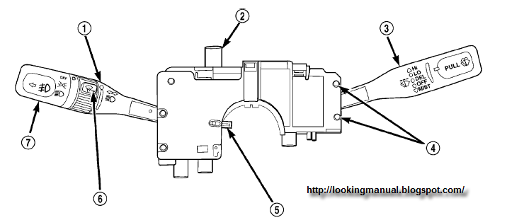
FRONT WINDSHIELD WIPERWASHER SWITCH LOCATION

FRONT WINDSHIELD WIPERWASHER SWITCH LOCATION
1 - TURN SIGNAL CONTROL STALK 5 - CANCELLING CAM
2 - HAZARD WARNING SWITCH 6 - PANEL DIMMER/INTERIOR LIGHT SWITCH
3 - WINDSHIELD WIPER/WASHER CONTROL 7 - EXTERIOR LIGHTING CONTROL/FOG LAMP
4 - WINDSHIELD WIPER/WASHER SWITCH RETAINING SCREWS. FRONT WINDSHIELD WASHER SYSTEM

This vehicle is equipped with an electrically operated windshield washer pump. The washers are operated by a switch in the multi-function switch control lever (Fig. 1). The lever is located on the right side of the steering column. The electric pump assembly is mounted directly to the reservoir. A permanently lubricated motor is coupled to an impeller type pump.

The pump and reservoir are serviced as separate assemblies. REAR WINDSHIELD WIPER SYSTEM The driver controls an electrically operated intermittent rear wiper system with the switch located on the instrument panel accessory switch bezel. The rear wiper is controlled by ignition switched battery current through a fuse in the fuse block, and will operate only when the ignition switch is in the Accessory or ON positions.

The intermittent rear wiper system allows the driver to select an intermittent wipe mode. The intermittent wipe mode delay time has a fixed delay interval of about four seconds between sweeps. This system also has a wipe-after-wash feature that operates the rear wiper for as long as the washer pump is energized, then provides about two additional sweeps of the wiper after the washer pump is de-energized. The rear wiper motor module operates on a separate non-switched battery current feed through a fuse in the fuse block.
Read More FRONT WINDSHIELD WIPERWASHER SWITCH LOCATION
Posted in |

CHRYSLER AIRBAG SYSTEM COMPONENT LOCATION

dual front airbag system
A dual front airbag system (Fig. 1) utilizes driver and passenger airbags. Both the driver and passenger airbags are certified to new federal regulations, which allows them to deploy with less force than prior airbags. The primary occupant restraints in this vehicle are the seat belts, which require active use by the vehicle occupants.

The front airbag system is a supplemental passive restraint that was designed and is intended to enhance the protection for the front seat occupants of the vehicle when used in conjunction with the seat belts. The driver airbag includes an inflatable airbag and an inflator unit behind a trim cover in the hub area of the steering wheel. The passenger airbag includes an inflatable airbag and an inflator unit behind an airbag door in the instrument panel above the glove box.

The dual front airbag system consists of the following components: ² Occupant Restraint Controller (ORC) ² Airbag indicator lamp. ² Clock Spring ² Driver and passenger airbags (including the airbag inflators).

1 - DRIVER AIRBAG
2 - CLOCK SPRING
3 - PASSENGER AIRBAG
4 - OCCUPANT RESTRAINT CONTROLLER (ORC)
Read More CHRYSLER AIRBAG SYSTEM COMPONENT LOCATION
Posted in |

Toyota 2L-T, 3L Engine Repair Manual Supplement

Toyota 2L-T, 3L Engine Repair Manual
this is Toyota 2L-T, 3L Engine Repair Manual inside is how to To assist you in finding your way through this manual, the Section Title and major heading are given at the top of every page. An INDEX is provided on the 1st page of each section to guide you to the item to be repaired. At the beginning of each section, PRECAUTIONS are given that pertain to all repair operations contained in that section. Read these precautions before starting any repair task. TROUBLESHOOTING tables are included for each system to help you diagnose the problem and find the cause. The repair for each possible cause is referenced in the remedy column to quickly lead you to the solution.

How to Use This Manual
The procedures are presented in a step-by-step format: #
• The illustration shows what to do and where to do it.
• The task heading tells what todo.
• The detailed text tells how to perform the task and gives other information such as specifications and warnings.
This format provides the experienced technician with a FAST TRACK to the information needed. The upper case task heading can be read at a glance when necessary, and the text below it provides detailed information. Important specifications and warnings always stand out in bold type.

GENERAL REPAIR INSTRUCTIONS
1. Use fender, seat and floor covers to keep the vehicle clean and prevent damage.
2. During disassembly, keep parts in order to facilitate reassembly.
3. Observe the following.
(a) Before performing electrical work, disconnect the negative (—) cable from the battery terminal.
(b) If it is necessary to disconnect the battery for inspection or repair, always disconnect the cable from the negative (—) terminal which is grounded to the vehicle body.
(c) To prevent damage to the battery terminal post, loos- en the terminal nut and raise the cable straight up without twisting or prying it.
(d) Clean the battery terminal posts and cable terminals with a shop rag. Do not scrape them with a file or other abrasive object.
(e) Install the cable terminal to the battery post with the nut loose, and tighten the nut after installation. Do not use a hammer to tap the terminal onto the post. (f) Be sure the cover for the positive (+) terminal is properly in place.
4. Check hose and wiring connectors to make sure that they are secure and correct.
5. Non-reusable parts
(a) Always replace cotter pins, gaskets, O-rings, oil seals, etc. with new ones.
(b) Non-reusable parts are indicated in the component illustrations by the ” ? ” symbol.

Download
Read More Toyota 2L-T, 3L Engine Repair Manual Supplement
Posted in |

Diesel maintenance manual 2008 Mercedes Benz AMG

2008 Mercedes Benz AMG service manual
In the pdf books including: – Engine Technical Data – Starting and Running – On the spot Maintenance – Checking the Engine – Scheduled Maintenance . this will show you how to maintenance your vehicle (2008 Mercedes Benz AMG ). please be carefully before you use it. we cannot quaranty.
you can download Diesel maintenance manual 2008 Mercedes Benz AMG from this source.
Read More Diesel maintenance manual 2008 Mercedes Benz AMG
Posted in |
Powered by Blogger.

Search